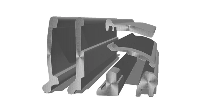
PRECISION THROUGH EVERY PROFILE

Precision shaped wire
Bring the material closer to the part.

Die design is central to shaped wire development. Based on the target contour, coordinate materials, passes, and die geometry to translate cross-sectional design into the forming process.

16Sample Case Set
10Material identification marks
65Performance photos
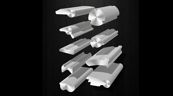
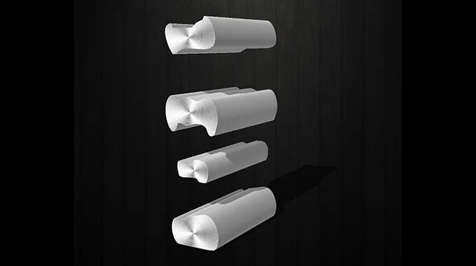
PROFILE ENGINEERING / 360°Locking block · Interactive 3D reference model
2D reconstruction reference model · Displays length shortened by 50% · Cross-section remains unchanged
01 / Search for products by cross-section02 / View actual development performance03 / Material selection in conjunction with subsequent processes04 / Communicate development requirements based on the drawing
WHY SHAPED WIRE

Pre-form the cross-section to make subsequent processing easier

As the wire profile approaches the target part, some material removal and forming steps can be reduced. The value depends on the specific cross-section, material, processing route, and batch size.

Conventional blanking route / schematic
Circular Billet→Material removal / forming→Target part

When the outer contour differs significantly, the final shape must be achieved through subsequent machining.

Irregular line route / schematic
Preformed Section→Required Processing→Target part

Pre-forming an adapted contour creates opportunities to reduce machining allowances and processes.

01

Use materials where they are needed

When the cross-section closely matches the part’s profile, excess metal and chips can often be reduced. Material utilization should be calculated based on actual unit weight, allowances, and scrap.

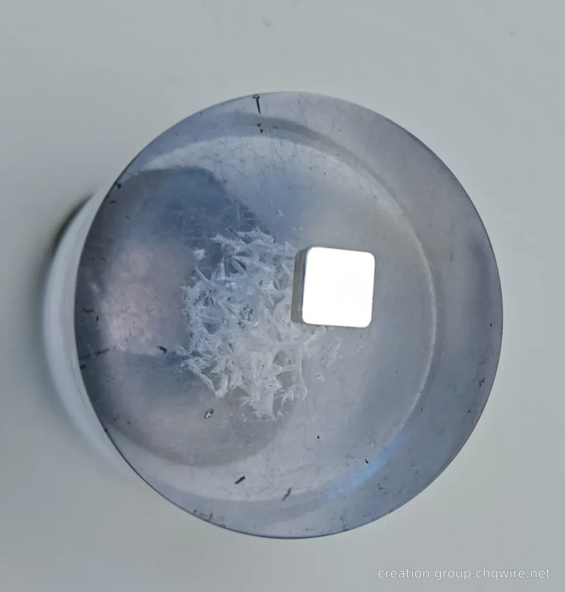
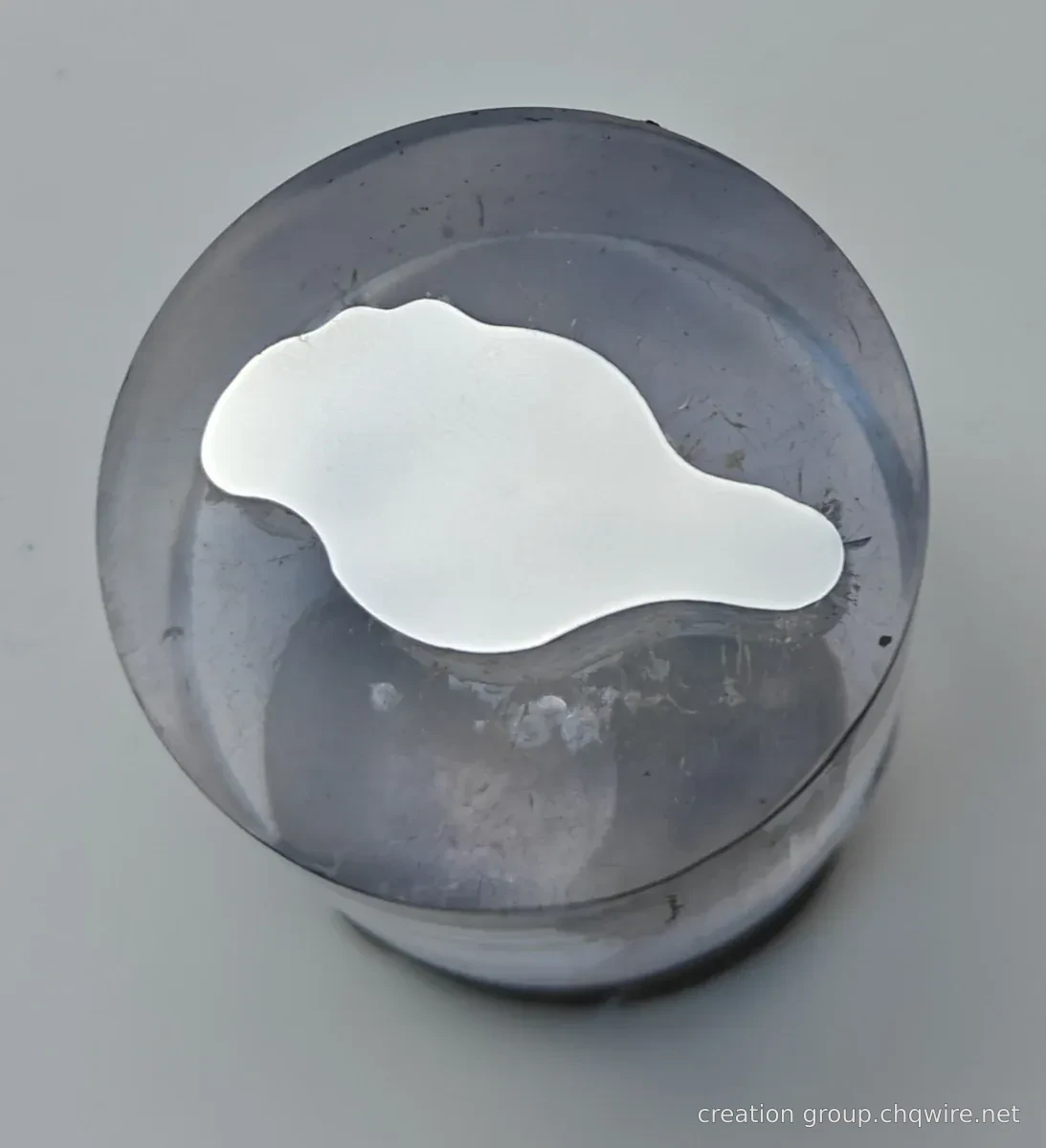
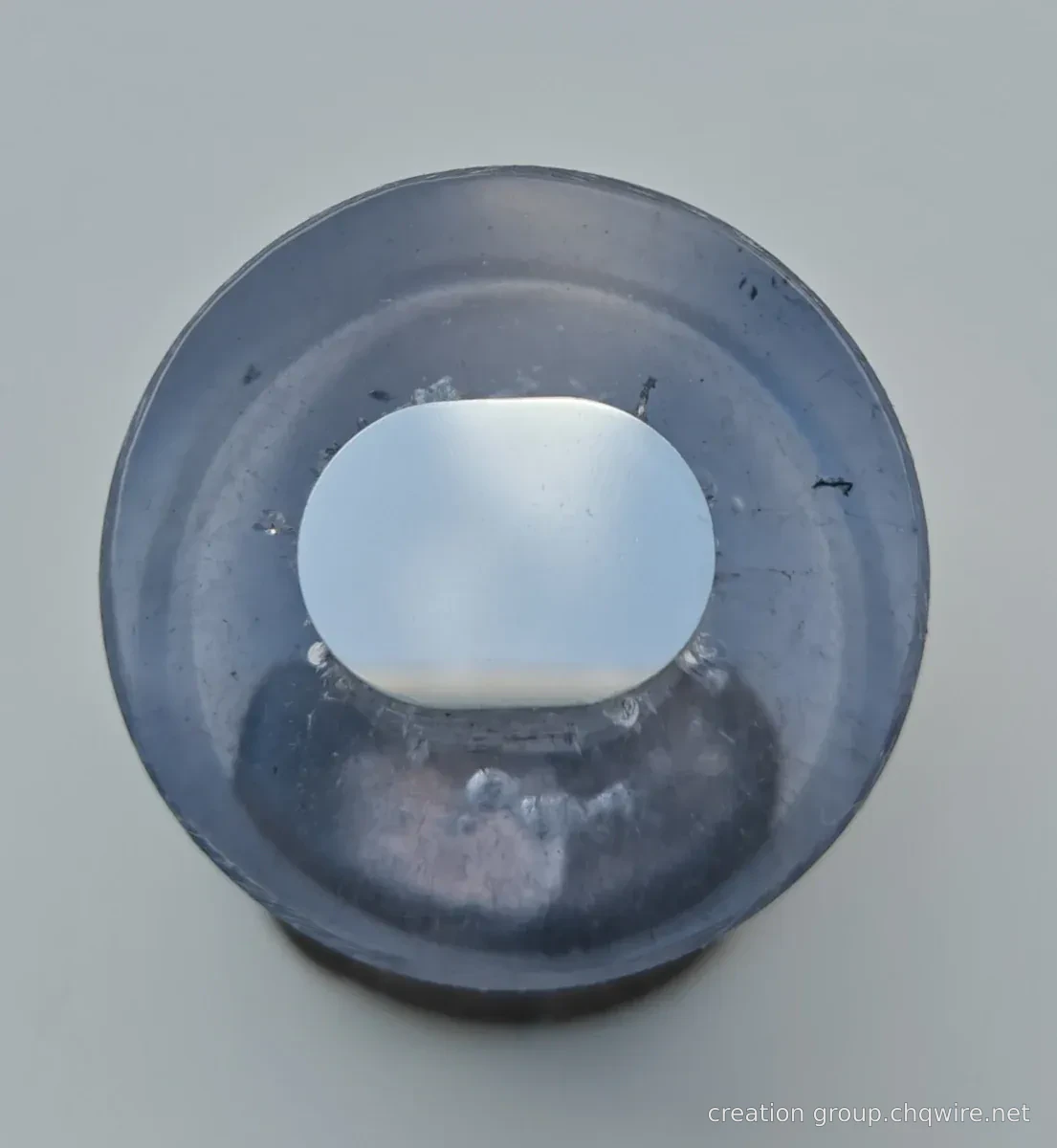
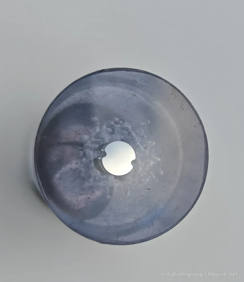
View the lock block’s irregular cross-section ↗
02

Reduce repetitive contour machining

By pre-forming repeating cross-sections along the wire length, it may be possible to reduce individual milling, slotting, or other material-removal processes while retaining necessary finishing.

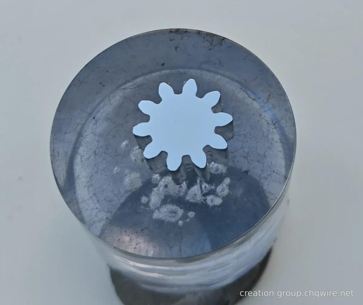
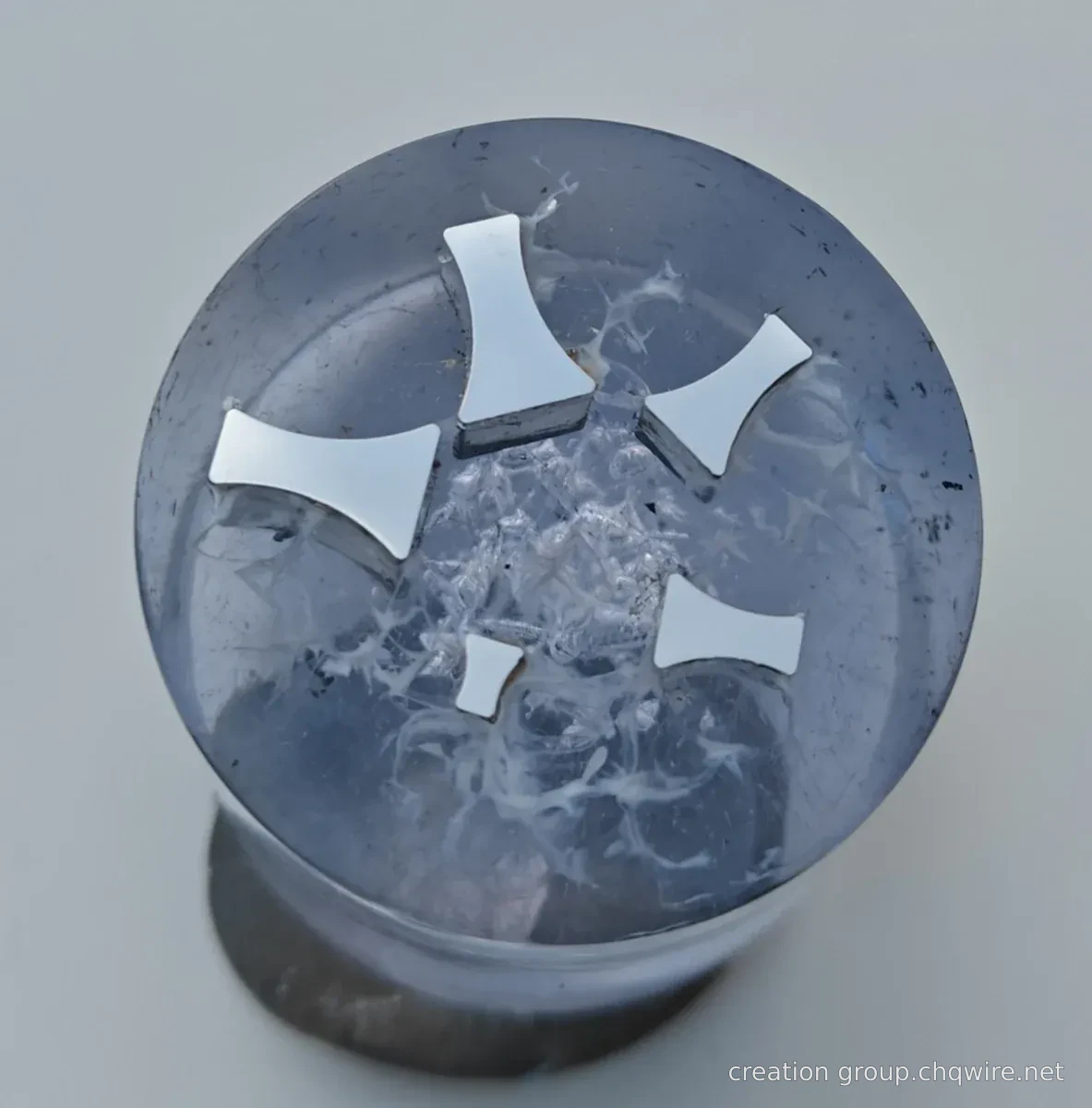
View the gear-shaped wire cross-section ↗
03

Design the shape together with subsequent processes

Review thickness distribution, fillets, and section orientation alongside subsequent stamping, bending, cold heading, or assembly requirements to ensure the incoming stock aligns with processing needs.

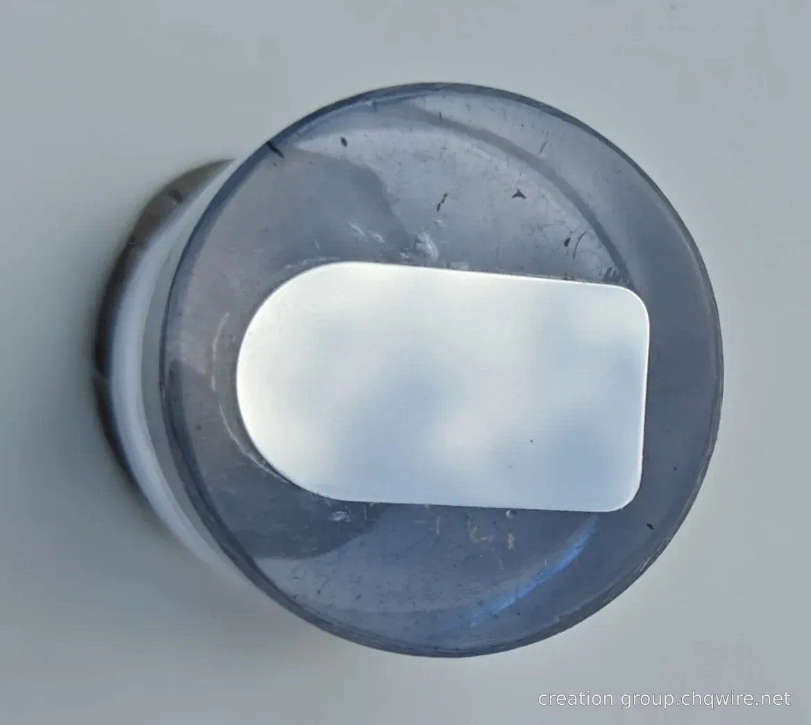
View U-shaped section ↗
04

Assess total cost based on qualified parts

Compare materials, cycle times, dies, tooling, scrap, and inspection together. When material usage and process savings outweigh development costs, the value of the solution becomes clearer.

Prepare your project evaluation data ↗
Which projects are worth prioritizing for evaluation?Repetitive cross-section partsContours with significant material removalCustomized requirements with a defined batch sizeNeed to match the incoming material for subsequent forming

The roadmap is for illustrating principles only and does not reflect actual material savings. The case links show corresponding cross-section samples but do not yet constitute proof that cost reductions or process substitutions have been achieved in these cases.

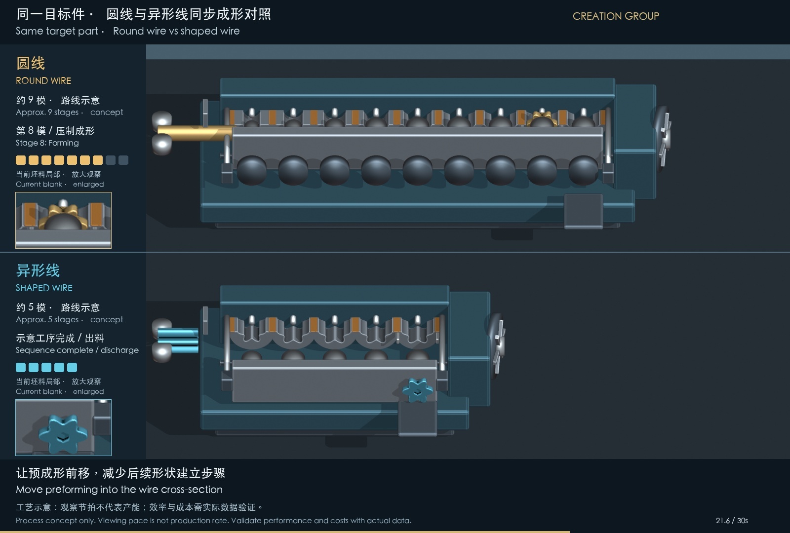
Cold Heading Routes and Cost Comparison

Round Wire vs. Shaped Wire: View Processes Side-by-Side and Calculate Costs Based on Actual Parameters.

View Cold Heading Forming Comparison and Cost Calculation ↗
Cold Heading Routes and Cost Comparison
TOOLING IS THE CORE

Proprietary Shaped-Wire Die Design Platform

Centered on shaped wire development, we have built an in-house, proprietary shaped die design platform that integrates contour verification from drawings, pass geometry planning, die aperture parameter design, and 3D sectioning visualization—ensuring seamless alignment among cross-sectional requirements, die structure, and engineering review within a single design workflow.

CREATION / TOOLING LABLocking block outer profile · Die cavity design schematic
PROFILE DIE
3D
DESIGN STUDY
Drag-to-rotate · Wheel-to-zoom
01 / CONTOUR

Confirm the target contour

Inlet sectionCompression zoneBearing landPost-relaxation zoneOutlet section
Profile Verification

Supports extraction of profile contours from drawings and manual correction, verifying boundaries, fillets, and dimensional datums to establish a well-defined target cross-section for initial die aperture design.

Pass planning

Enables viewing of cross-sections, area changes, and area reduction ratios per pass—as specified by process engineers—to facilitate comparison and discussion of forming strategies.

Preliminary die design

Correlates compression half-angle, bearing land, insert outer diameter, and insert thickness; verifies cavity zoning and spatial relationships, with intuitive validation via 3D sectioning.

Trial Mold Confirmation

Differentiates between target wire tolerance and die aperture machining tolerance; incorporates the initial design into engineering review and refines it using material condition, springback behavior, and trial-die measurement data.

The demonstration outer contour is taken from the home page lock block reference model, and a die cavity schematic is constructed based on 128 angular points; local contours exhibit some discretization approximation. The entry is shown as a scaled-up representation; core and compression zone parameters are for illustrative purposes only and do not constitute a formal die design. The axial hole in the model does not indicate that it was formed by pulling through the outer contour. Actual passes, compensation, and manufacturing dimensions must be verified through engineering review and trial tooling.

PROFILE EXPLORER

The cross-section is the starting point; functionality is the goal

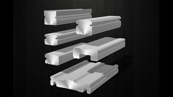
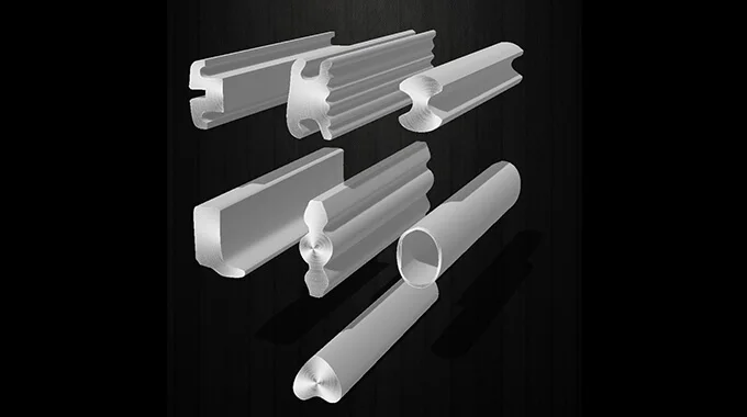
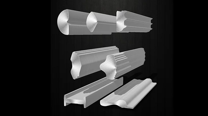
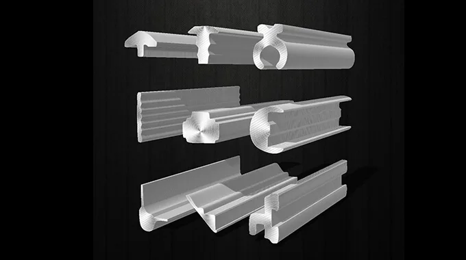
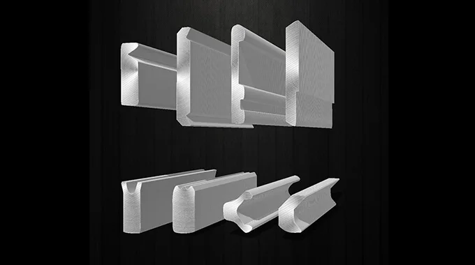
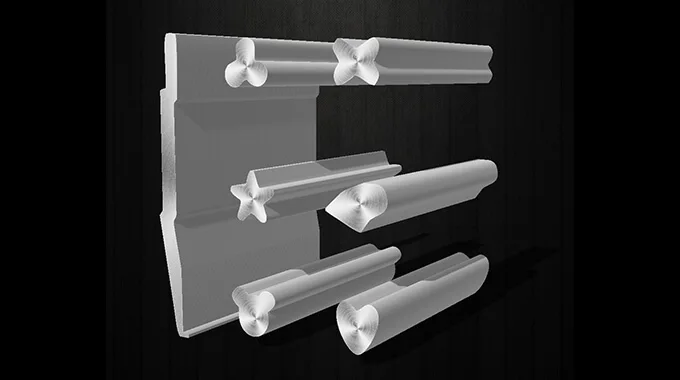
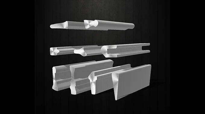
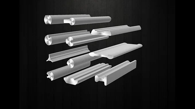
Quickly browse related samples by cross-section. Complex shapes’ dimensions, fillets, and material conditions require further evaluation in conjunction with drawings.

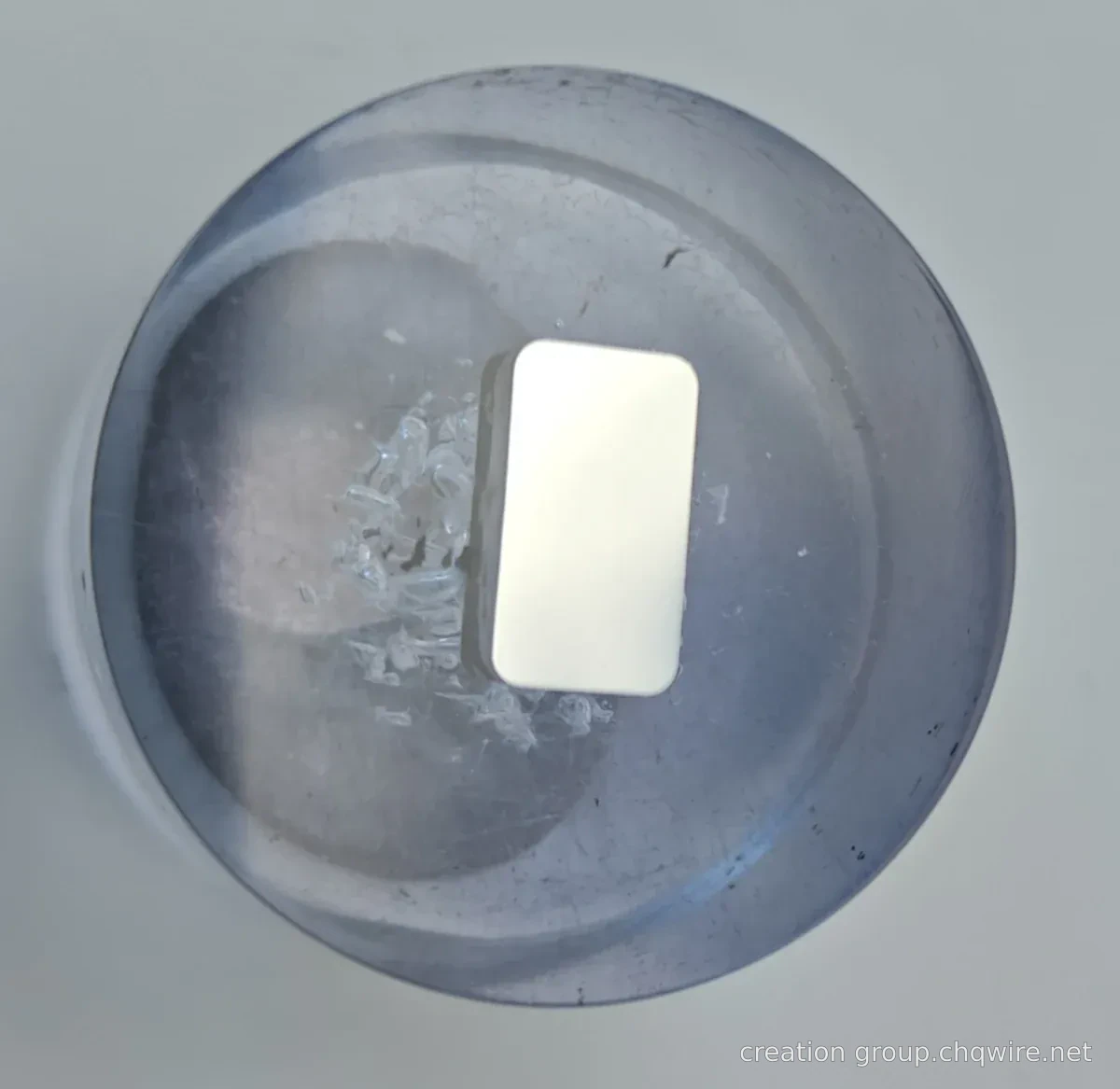
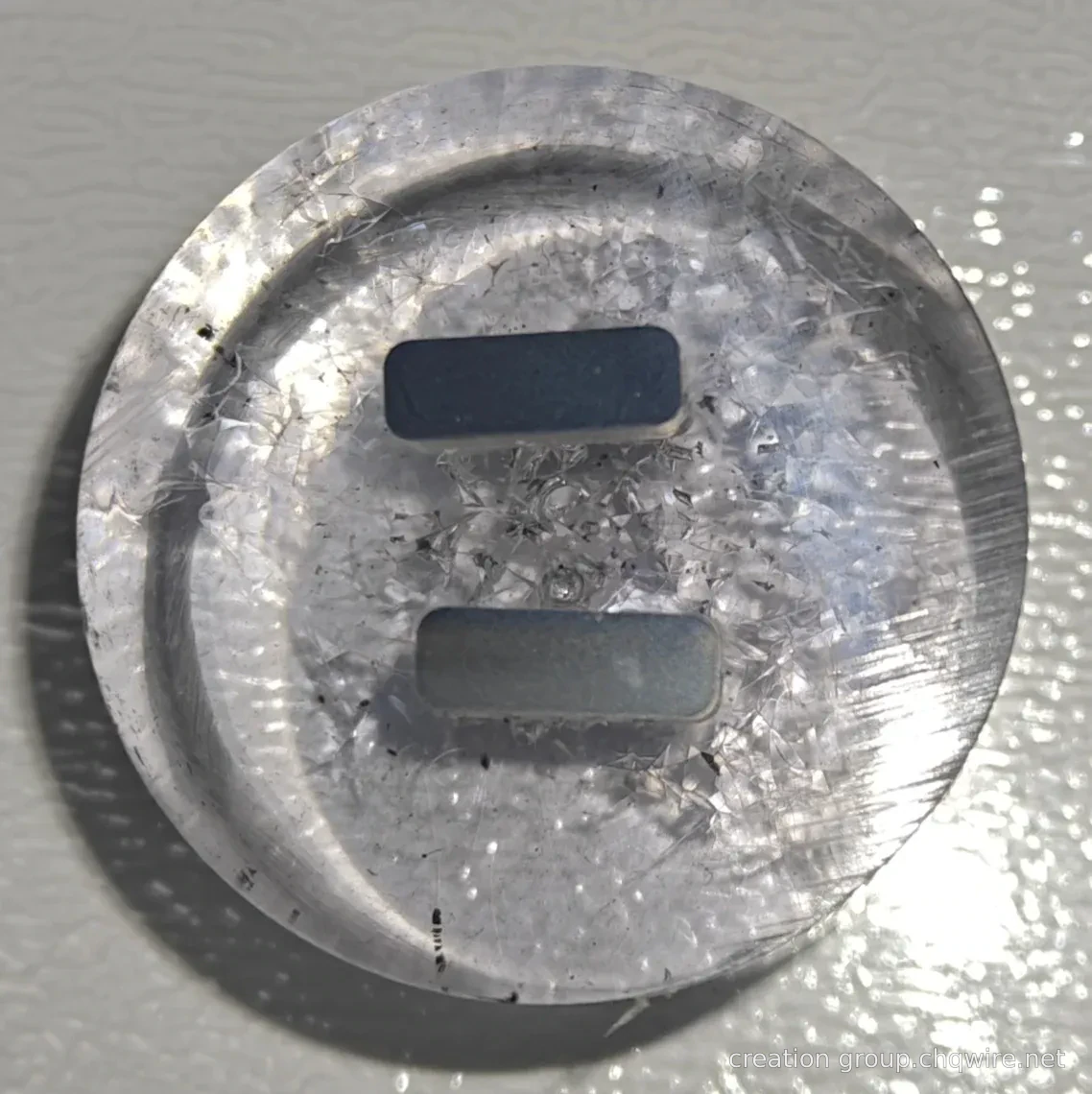
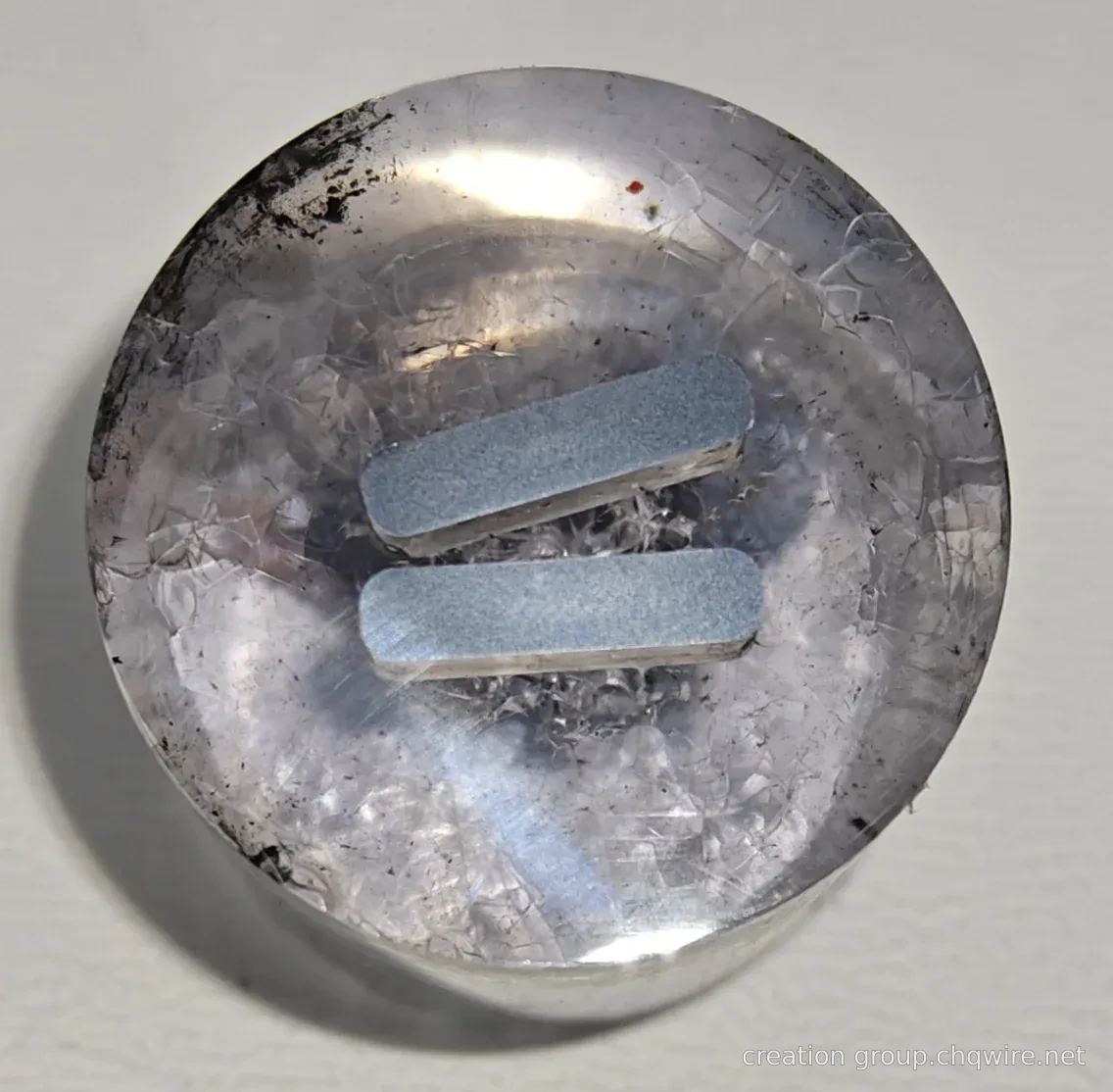
Browse development examples and existing application profiles together. Each entry retains its own material, dimensions and source; selection is confirmed through technical review.

DEVELOPMENT PORTFOLIO

Cross-section and product · Development performance

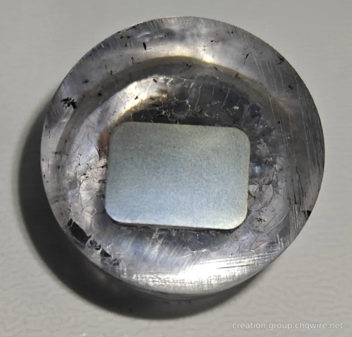
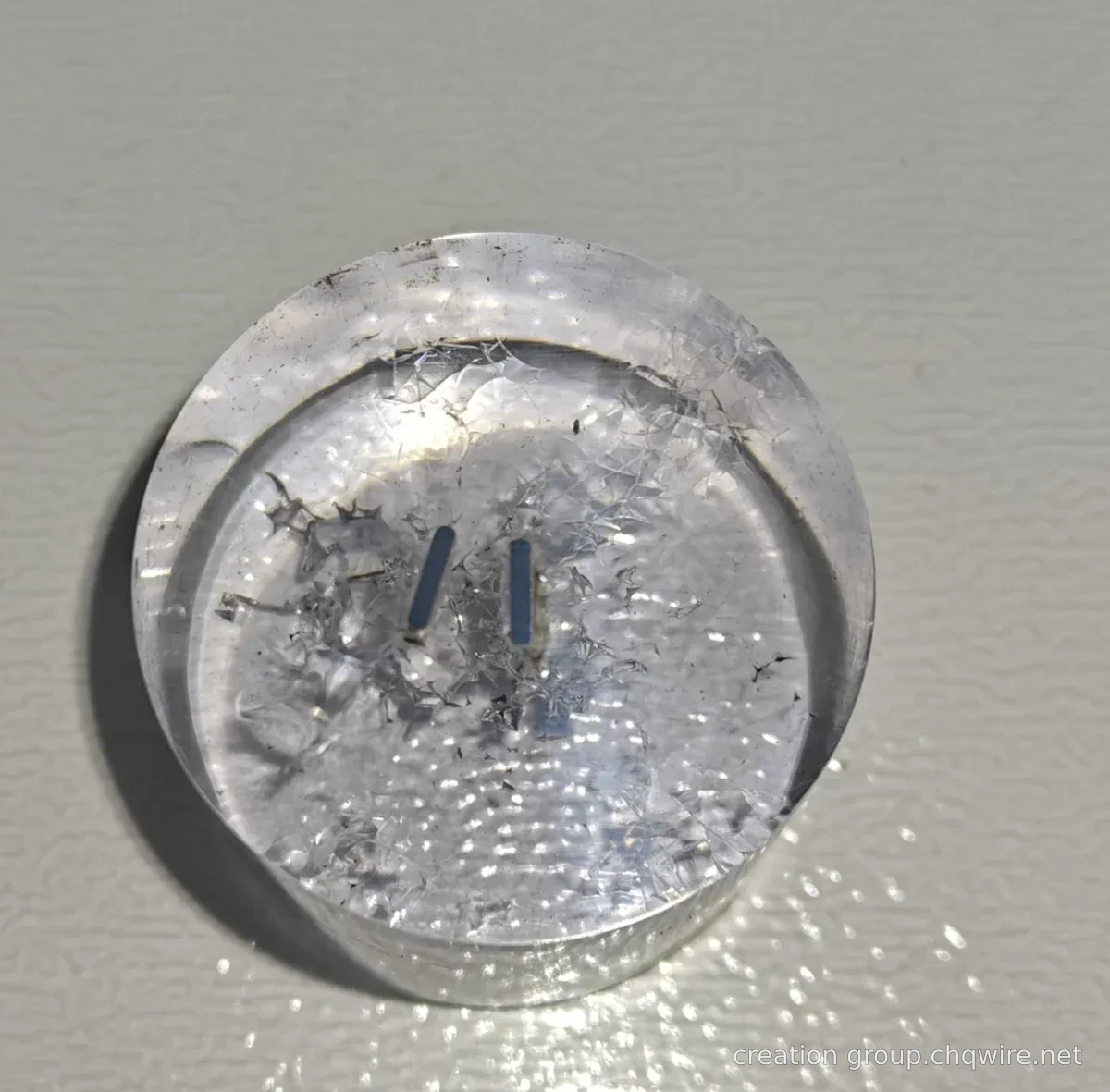
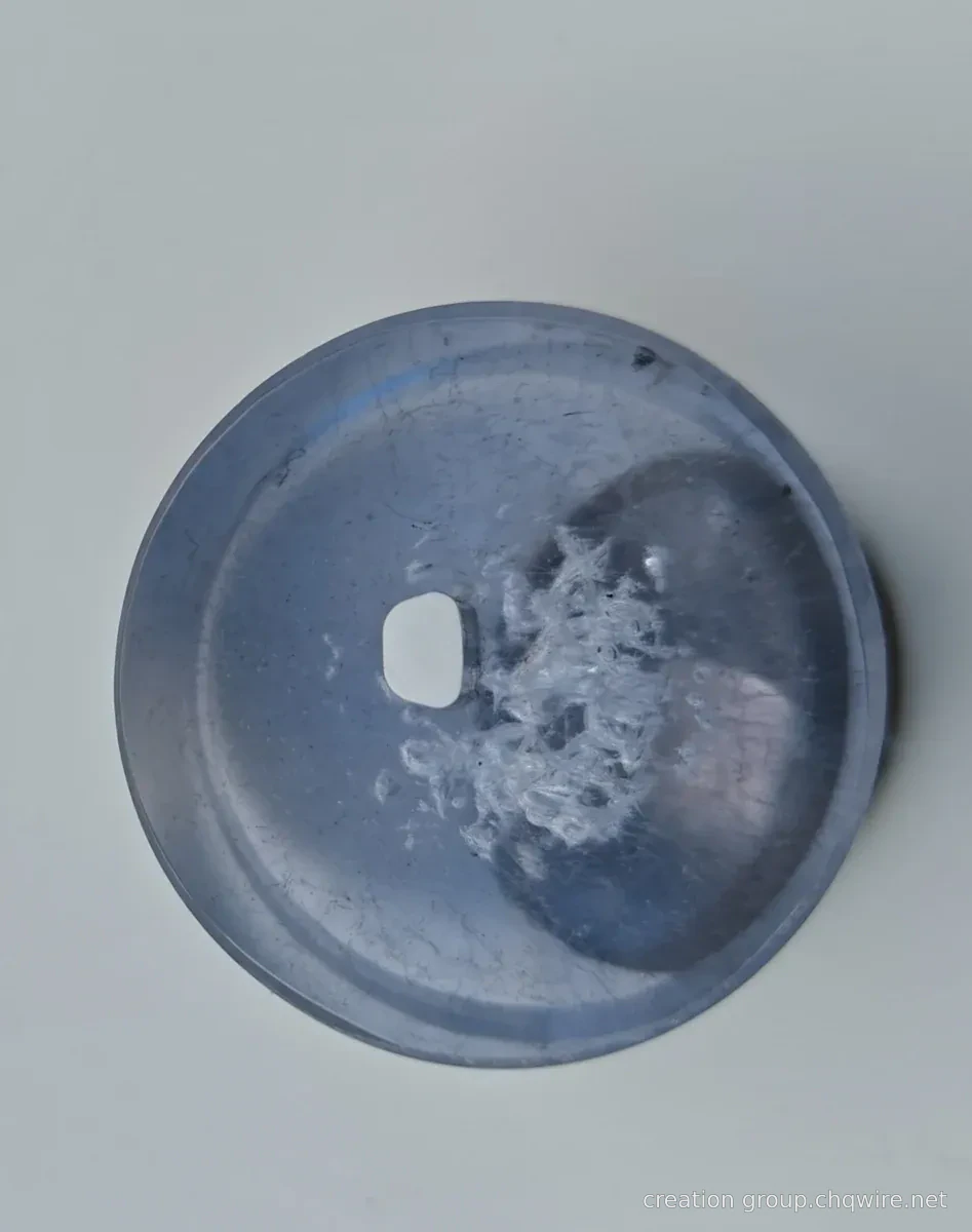
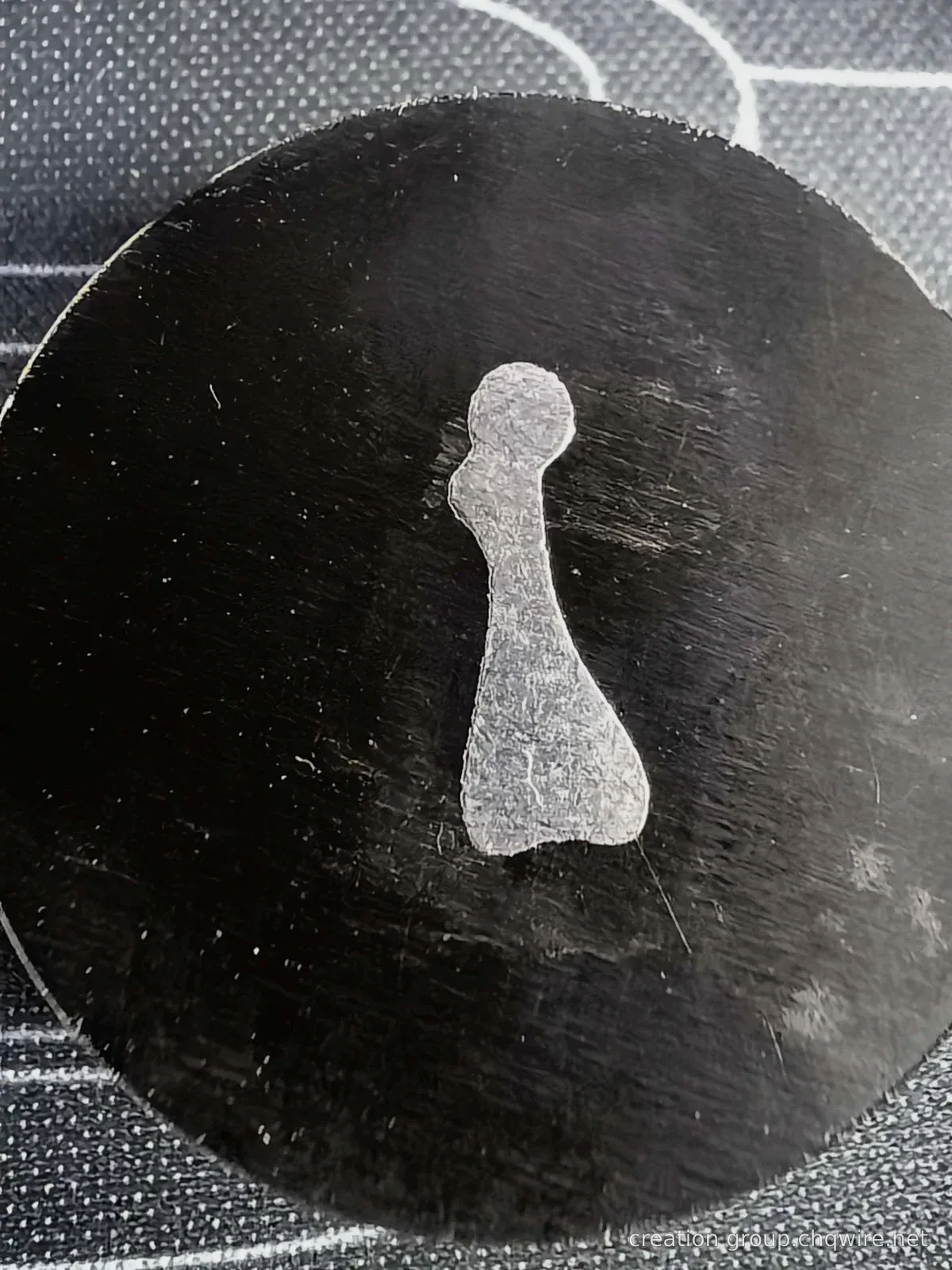
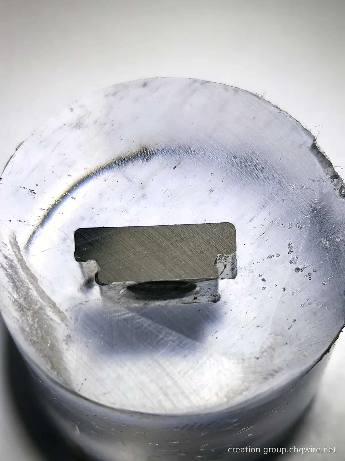
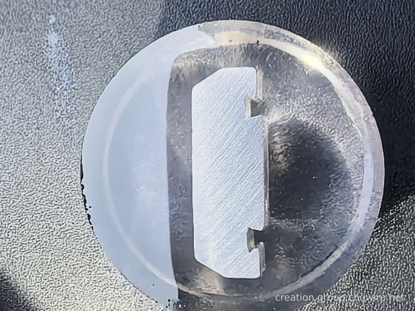
From basic square-flat shapes to complex profiles, examine embedded cross-sections, wire samples, and measurement photos. Click on each case to learn about geometric features and key points for technical communication.

Development performance · 16

Application profiles · 11

APPLICATION DIRECTORY

Industry applications

Confirm technical requirements based on the drawing

Automotive shaped wireMachinery shaped wireConstruction shaped wireCustom shaped wire
MATERIAL × PROFILE

Choose the shape, but also choose the material condition

The following material designations come from existing cases. Material selection should be confirmed in conjunction with subsequent forming, processing, and service requirements.

The grade retains the original designation without equivalent substitution across standards. Dimensions are nominal values from the catalog; specific standards, composition, and delivery condition will be confirmed per project.

DESIGN FOR THE NEXT OPERATION

Link cross-section design with subsequent processes

The value of shaped wire must be evaluated within the context of the specific part and processing route. Approaching the target shape is only the first step.

01 / NEAR-NET GEOMETRY

Close to the target contour

Assess the possibility of replacing certain material-removal operations with pre-formed cross-sections, while retaining necessary machining allowances and locating references.

  • Correspondence between the target part and the wire cross-section
  • Allowance, fillet radius, and local thickness variations
  • Material utilization is compared based on actual mass
02 / DOWNSTREAM PROCESS

Adapt to subsequent processing

Translate cold heading, stamping, bending, cutting, or heat treatment requirements into wire delivery specifications.

  • Material condition and forming performance requirements
  • Surface, lubrication, and machining direction
  • Coil, straight bar, and straightening requirements
03 / TOTAL PART COST

Compare qualified part costs

Comprehensively compare materials, processes, dies, scrap, and inspections to determine whether the development proposal holds practical value.

  • Individual piece actual mass and yield rate
  • Process cycle time and tool/die consumption
  • Development investment and projected batch size
PROFILE CONTROL

Incorporate “precision” into the explicit technical requirements

Tolerances must correspond to specific dimensions, materials, shapes, and measurement methods. During drawing reviews, we recommend jointly confirming the following items.

Bottom Width BTop width bhαGeometric annotations are for illustrative purposes only; no actual dimensions or tolerances are provided.
Cross-sectional geometryWidth, thickness, angles, fillets, openings, and complete contour
Lengthwise directionStraightness, torsion, bending direction, and cut-to-length requirements
Materials and conditionsGrade standards, performance, heat treatment, and surface condition
Acceptance criteriaMeasurement datums, inspection methods, sampling, and record-keeping
Delivery conditionsCoil or straight bar, packaging, and batch traceability requirements
CUSTOM PROFILE DEVELOPMENT

Define each development step based on your part.

From the target cross-section to sample validation, evaluate materials, dimensions, delivery condition, and downstream processing requirements together.

01 / REQUIREMENTS

Drawing and requirements assessment

Confirm the cross-sectional geometry, critical tolerances, material requirements, and downstream processes to clarify the technical objectives of development.

02 / SAMPLE DEVELOPMENT

Forming plan and sampling

Discuss forming routes in conjunction with specific materials and cross-sections, and verify shape and delivery condition using physical samples.

03 / VALIDATION

Verify according to agreed requirements

Verify samples against agreed-upon inspection items and advance development based on the customer’s downstream processing outcomes.

Specific solutions, inspection items, and delivery conditions are subject to mutually confirmed project requirements.

ENGINEERING DESK

Turning an idea into clear requirements

Prepare cross-sectional drawings, material grades, critical tolerances, downstream processes, and estimated usage to make the development assessment more concrete.

Submit technical requirements ↗

Provide drawings and technical requirements to discuss development options suitable for your specific project.

Rapid estimation of linear weight

Weight per meter kg/m = Cross-sectional area mm² × Density g/cm³ ÷ 1000
7.85 is an example density; actual values depend on the material. Does not include dimensional deviations.

WhatsApp Technical enquiry →
Image and content use · Creation Group