
PROFILE DEVELOPMENT / 45#
Automotive seat-belt locking block profile wire
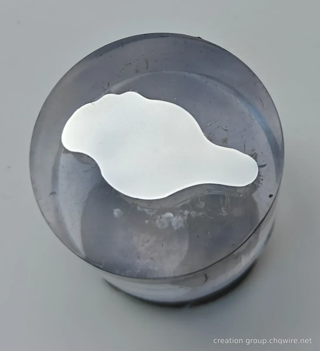
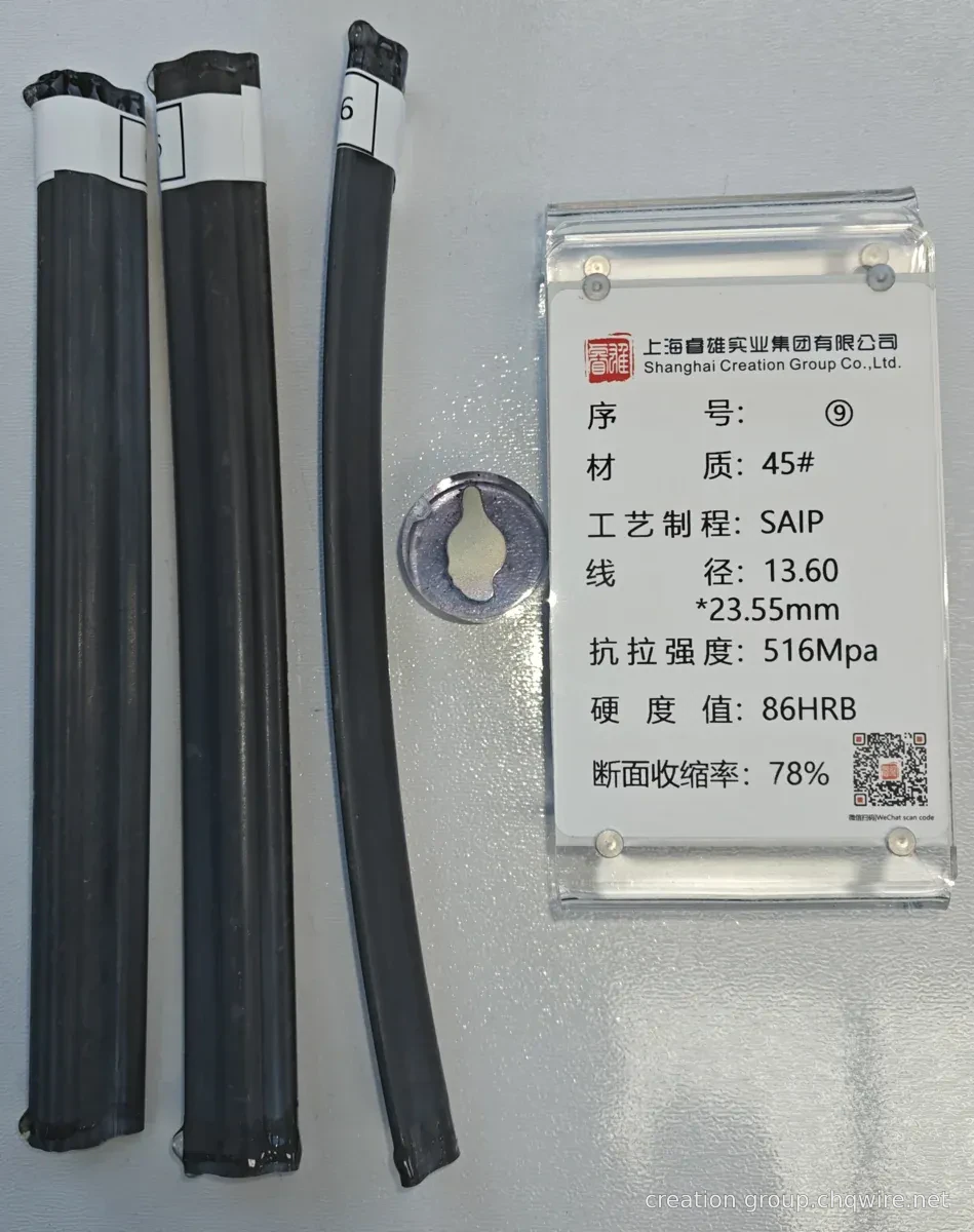
45# Shaped Wire for Automotive Seat-Belt Locking Block: Locking block shaped sample record. The locking block sample exhibits an asymmetric shaped profile; review focuses on local radii, orientation relationships, and datum features—not reducible to a simple rectangular or flat cross-section.
Geometric Focus Points
Asymmetric contour, local arcs, and positioning references
Contour measurement datums, local curvature, and section orientation
Confirm technical requirements based on the drawing
Cross-sectional features and review points
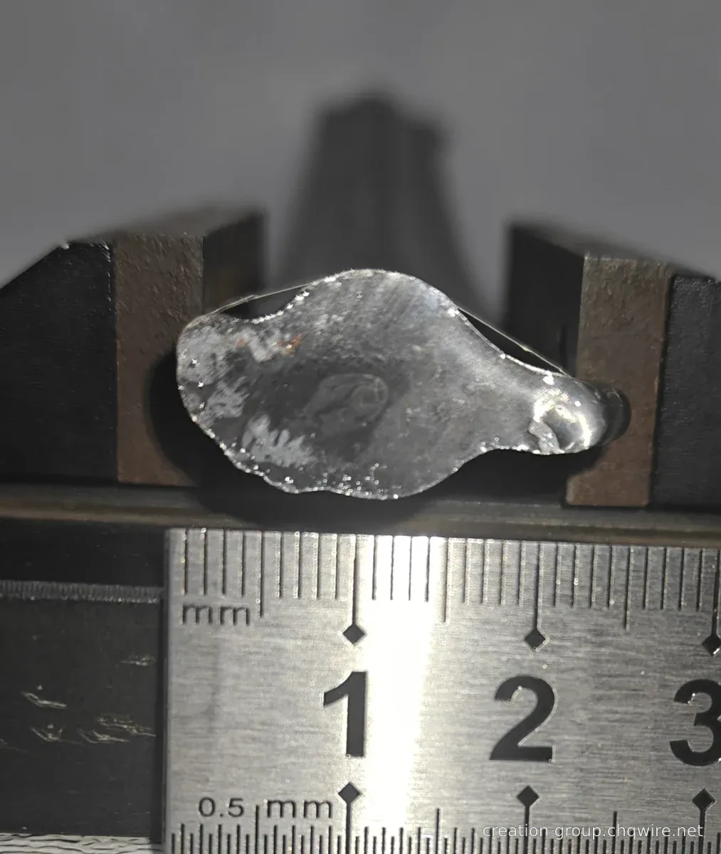
The locking block sample exhibits an asymmetric irregular profile; review focuses on local arcs, orientation relationships, and positioning datums—simple rectangular or flat cross-section assumptions are invalid.
Drawings and measurement requirements
Recommend annotating target cross-section together with locating surfaces, functional contact zones, and local fillets; for asymmetric contours, explicitly define cross-sectional orientation and corresponding measurement datum.
Delivery and subsequent processing
Mold schematics or 3D representations on this page serve geometric communication only and do not replace formal die-orifice design or trial-die records; actual processing and delivery requirements must be confirmed per project.
Documentation basis and scope of confirmation
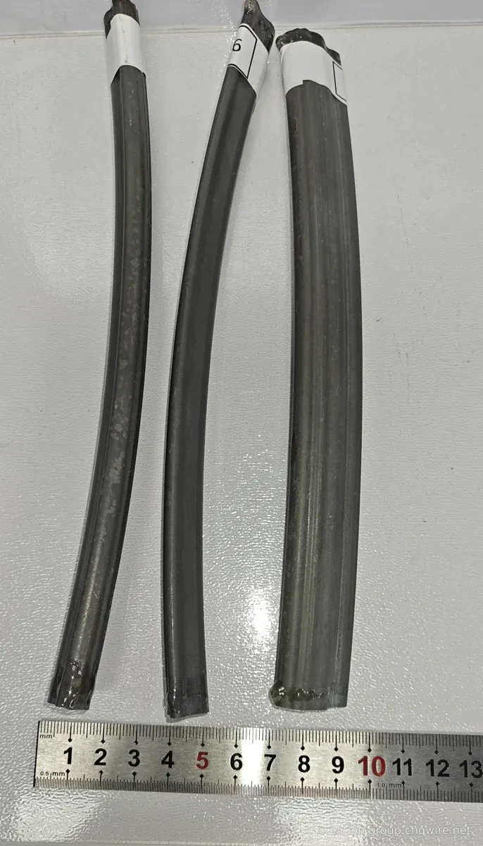
Data originates from this case’s catalog and internal sample photographs; catalog dimensions are nominal values, and photographs do not substitute formal inspection reports. Material standards, mechanical properties, heat treatment, supply conditions, and acceptance criteria must be confirmed per project.
Photo recording
Development Q&A
Why must orientation be indicated for the locking block shaped cross-section?
Local dimensions and positioning relationships for asymmetric profiles depend on cross-sectional orientation; consistent orientation datums must be used across drawings, measurement, and subsequent machining.
Does the die schematic represent the official manufacturing dimensions?
No. The illustration clarifies contour-to-die-cavity relationship only; formal manufacturing dimensions and compensation require engineering verification and trial-die confirmation.
Related cross-sectional cases
Material data and technical communication
Technical requirements must include cross-sectional drawing and revision, critical tolerances, subsequent processing steps, delivery form, and inspection requirements.
View material selection documentation Submit technical requirements ↗