
PROFILE DEVELOPMENT / Q235
Shaped bearing-cage pillars
Q235 Shaped Bearing-Cage Pillar: This shaped pillar is used in bearing cages. Review focuses on multi-sided profile, corners, local thickness, and assembly fit with the cage; specific dimensions and acceptance criteria to be confirmed per drawing.

Geometric Focus Points
Polygonal profile, corners, and local thickness
Cross-sectional orientation, local dimensions, and profile datum
Confirm technical requirements based on the drawing
Cross-sectional features and review points
This shaped bearing-cage pillar is used in bearing cages. Review focuses on multi-edge contour, corner geometry, local thickness, and assembly fit with the cage; specific dimensions and acceptance criteria to be confirmed per drawing.
Drawings and measurement requirements
Recommend providing complete cross-sectional drawing, local dimensions, and datum; clearly define all corner transitions and contour orientation; functional surfaces must align with downstream mating requirements.
Delivery and subsequent processing
If the project involves load-bearing, joining, or assembly functions, corresponding design, material condition, and validation requirements must be provided; structural suitability must not be inferred from column naming alone.
Documentation basis and scope of confirmation
Data originates from this case’s catalog and internal sample photographs; catalog dimensions are nominal values, and photographs do not substitute formal inspection reports. Material standards, mechanical properties, heat treatment, supply conditions, and acceptance criteria must be confirmed per project.
Photo recording
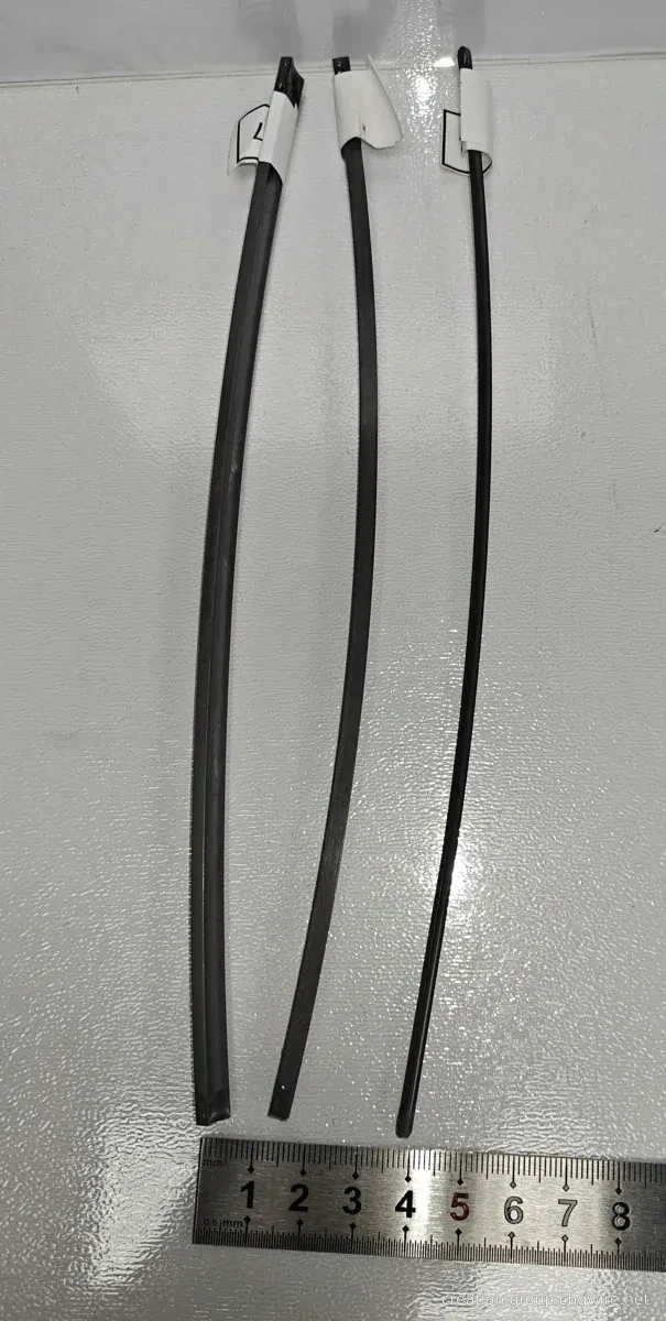
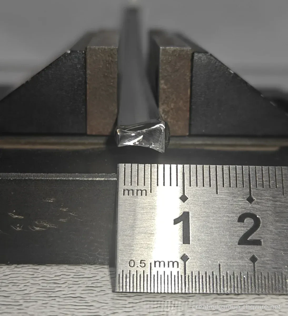
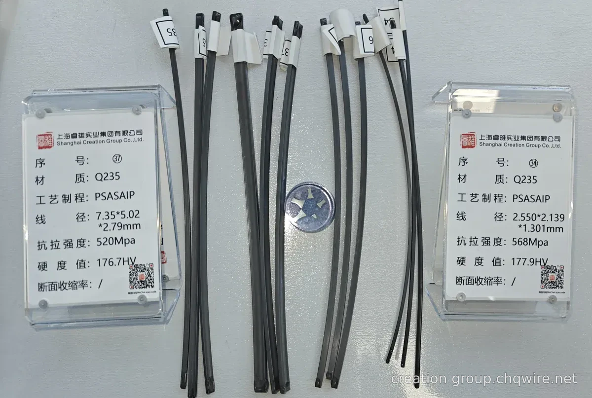
Development Q&A
Does the column name indicate direct suitability for load-bearing structural applications?
No. This is a sample catalog name only; load-bearing application requires supporting design criteria, material specifications, and validation documentation.
How is the inspection datum established for multi-edge column cross-sections?
First specify the locating surface and cross-sectional orientation in the approved drawing, then annotate inspection locations for local thickness, corners, and overall contour.
Related cross-sectional cases
Material data and technical communication
Technical requirements must include cross-sectional drawing and revision, critical tolerances, subsequent processing steps, delivery form, and inspection requirements.
View material selection documentation Submit technical requirements ↗