
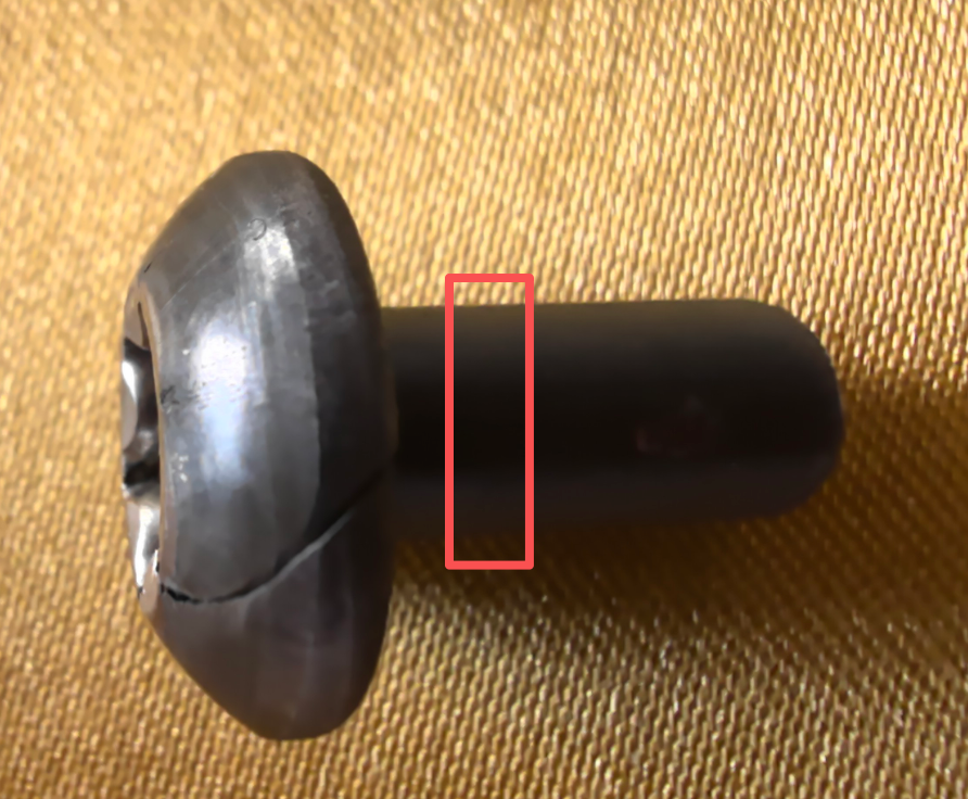
After a cold-headed part cracks, when the specimen is cut open and examined under a microscope, black particles are found near the crack. At the site, it’s easy to conclude: “We’ve found the cause—it’s caused by inclusions.”
This conclusion may be correct, but it could also be premature. Inclusions might contribute to crack formation, but moving from “observing an anomaly” to “proving that it caused failure” requires evidence that supports each other. Demonstrating that particles contributed to cracking does not mean the entire batch of material is defective, nor does it mean responsibility has been clearly assigned.
First, separate the four questions
| Question | Required Judgment |
|---|---|
| What was observed? | Identification of particles, voids, microstructure, or sample preparation artifacts |
| Does the material meet requirements? | Evaluation of compliance based on standards, agreements, and valid inspections |
| Why did it crack? | Determination of crack initiation, propagation, and the roles of material and process |
| How is responsibility determined? | Assessment of supply agreements, defect origins, manufacturing processes, and causal relationships |
The four questions are interrelated, but the answer to one cannot substitute for the others.
I. The presence of inclusions in steel does not necessarily mean the material is non-conforming
Non-metallic inclusions in steel can originate from deoxidation reactions, solidification processes, or external contaminants. When evaluating inclusions, consider their size, morphology, quantity, distribution, and intended application; cleanliness should not be judged solely by whether “black spots” are present.
Whether a material is acceptable depends on applicable product standards, technical specifications in the purchase order, and mutually agreed acceptance criteria. ASTM E45 is a standard method for examining and describing inclusions, but it does not provide uniform pass/fail limits suitable for all applications.[1]
Conversely, passing an inclusion rating does not imply that all cracking incidents are unrelated to the material. A pass judgment applies only under specified sampling and testing conditions; the local material condition, deformation history, and service requirements of a specific component still require separate consideration.
II. Black Particles Under the Microscope Are Not Necessarily Inclusions
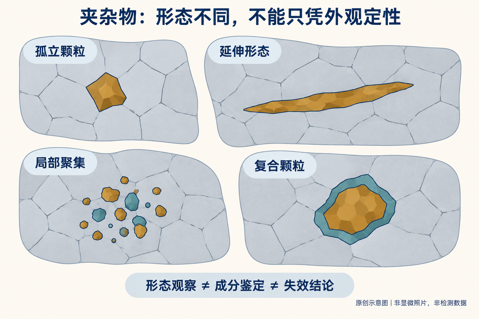
The black areas may be inclusions, but they could also be voids, pits left by particle detachment, scratches, corrosion pits, or contamination. Second-phase particles such as carbides and nitrides should not be automatically equated with harmful non-metallic inclusions. "Black spots" are merely observational descriptions and do not yet constitute a characterization of their nature.
The morphological categories in rating charts do not necessarily correspond to the actual chemical composition. ASTM E45 explicitly distinguishes between morphological classification and chemical properties: similar particle appearances do not imply identical compositions.[1]
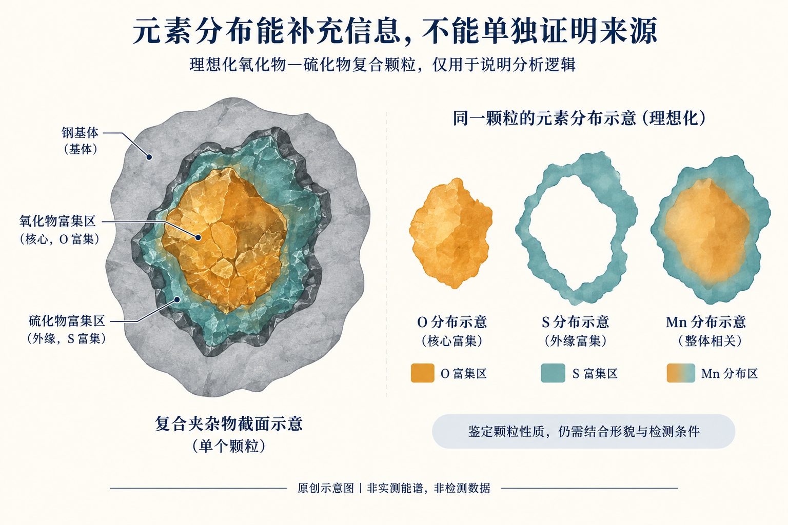
Scanning electron microscopy (SEM) combined with energy-dispersive spectroscopy (EDS) can provide additional information on morphology and elemental composition, but elemental peaks alone cannot prove that a particle originates from a specific steel plant, refractory material, or production process. Particle size, surrounding matrix, surface condition, and analysis conditions all influence interpretation. Elemental data must be corroborated by morphological features and contextual evidence.[3]
III. Why Inclusions May Contribute to Cold Heading Cracking
Particles may differ from the steel matrix in terms of deformation capability, stiffness, and interfacial characteristics. During deformation, particles themselves may fracture, or debonding may occur at the particle–matrix interface, forming microvoids. Under appropriate local stress and strain conditions, these voids can grow and coalesce, eventually leading to crack formation.
Although cold heading is predominantly a compressive forming process, it does not mean that every localized region of the part is always under compression. Material flow, geometric constraints, and friction can alter local stress states, and tensile or shear stresses may still contribute to damage.
Research on ductile failure within cold-headed steel components has observed and discussed the relationship between inclusion or second-phase particle fracture, interfacial debonding, and microvoid damage.[4] This indicates that such phenomena have the potential to contribute to cracking, but it does not prove that all cold heading cracks follow the same mechanism. The location, morphology, and local deformation conditions of particles are more relevant to the actual problem than simply counting the number of particles.
IV. Why You Shouldn't Focus Solely on Quantity, Size, or a Single Rating Number
A small number of isolated particles and locally clustered particles aligned along a particular direction cannot have their risk compared simply by counting the total number. Particles of similar size located in different regions and oriented differently may also have varying effects.
The fact that manganese sulfide can undergo some deformation does not mean it is harmless under all operating conditions; similarly, hard oxides do not necessarily constitute the cause of cracking in this instance. Particle classification provides clues for assessment but cannot replace specific evidence of failure.
Inclusion ratings are not a universal "hazard score." Inspection methods, section orientation, observation area, reporting practices, and material condition all influence the results. Numbers obtained from different methods or versions cannot be directly compared without considering the specific conditions.
V. Why Local Inclusion Risks Cannot Be Excluded Even with a Passing Rating
The interior of a material is not entirely uniform, and limited sampling cannot cover every location within an entire coil of wire. A routine rating performed over a specified area addresses a different statistical issue than the occasional presence of large particles or foreign inclusions.
ASTM E1245 distinguishes between the applicable scope and limitations of automated image analysis: statistical characterization of typical inclusion populations should not be used to directly substitute for evaluating rare, extraneous inclusions.[2] Similarly, finding abnormal particles on a failed component does not allow one to infer the statistical distribution across an entire batch of material.
After cold heading, particles may have rotated, elongated, fractured, or detached, and voids may have formed around them. Therefore, observations made on a failed part cannot be treated as an inclusion rating reflecting the original supplied condition without proper explanation.
VI. Why the presence of inclusions near a crack does not yet prove they are the cause of cracking
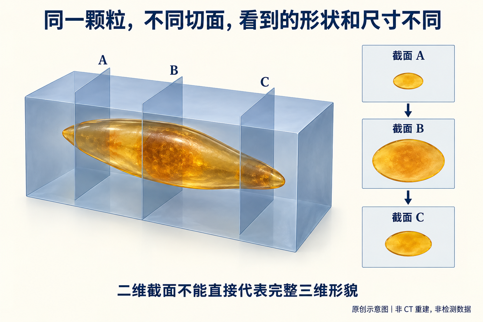
The relationship between "being near the crack" and "causing the crack" still lacks causal evidence. At least several different explanations exist: particles may have contributed to crack initiation; the crack may have formed elsewhere and then passed through the particle; the particle may promote crack propagation without being the origin point; on a two-dimensional cross-section, the proximity might be misleading, as the true three-dimensional spatial relationship remains unclear; or contamination could have been introduced after the crack opened.
To make a judgment, it is necessary to correlate crack origins, damage morphology, the spatial relationship between particles and cracks, material behavior, and actual production anomalies. Particles adjacent to cracks deserve attention, but mere proximity alone is insufficient to determine the primary cause of cracking.
Similarly, the absence of inclusions on a single cross-section does not definitively rule out their influence. Actual damage occurs in three-dimensional space, so the cross-section may not pass through critical locations, and particles may also detach during sample preparation.
VII. Material factors and process factors can act together
Failure cannot always be simply attributed to either "poor material quality" or "faulty customer process." Local material weaknesses may arise from interactions among microstructure, deformation paths, friction, and material flow; conversely, process abnormalities can subject otherwise acceptable materials to localized damage beyond their intended tolerance range.
Once inclusions are identified, discussions about surface defects, microstructural conditions, cutting, lubrication, and die-related factors should not cease. Even if process adjustments can improve outcomes, this does not negate previously confirmed nonconformities in the material.
Two conclusions must be clearly distinguished here: If the material fails to meet specifications, even if its role in causing the current cracking has not yet been proven, it still constitutes a compliance issue. Conversely, if the material meets specifications but evidence indicates that certain local characteristics contributed to cracking, the suitability and risks in practical applications still require evaluation. Evaluating each factor separately and then clarifying their interrelationship helps avoid confusion regarding responsibility and causality.
8. What can inclusion analysis software help with, and what cannot it replace?
Under the conditions of proper calibration, correct identification, and an appropriate field of view, image analysis can improve the efficiency and consistency of projecting measurements such as size, area, aspect ratio, count, and distribution statistics.
However, software may mistakenly identify scratches, voids, or pits caused by particle detachment as inclusions. Two-dimensional projections or cross-sectional dimensions also do not equate to the complete three-dimensional morphology of particles; measurements taken on a single plane cannot directly provide all spatial information.[2]
Image measurement, standard inspection and conformity assessment, and failure cause determination are three distinct levels. Software cannot bypass the latter two. The mere appearance of a standard name on the interface does not prove that sampling, sample preparation, observation, and reporting have fully met that standard.
9. To what level should professional conclusions be stated?
The strength of a conclusion should match the strength of the evidence. When only optical appearance is available, one can state “suspected inclusion or void, nature to be confirmed.” If the particle’s nature has been confirmed but its origin remains uncertain, one might write, “may have contributed to localized damage, but insufficient to establish it as the primary crack initiation cause.”
A basis exists to conclude that a particle participated in crack initiation—and to separately discuss other contributing factors—only when the particle found at the crack origin, the local damage morphology, and the underlying mechanism are mutually consistent. If thorough testing demonstrates that the material fails to meet specified requirements, then the non-conformity can be clearly identified while separately evaluating its causal relationship to the current cracking event.
Detecting aluminum and oxygen elements near a crack still involves multiple steps beyond particle identification, source attribution, process causation, and failure cause determination before concluding that poor deoxidation in the steel plant led to the cracking. Careful wording does not mean avoiding conclusions; rather, it ensures that conclusions remain grounded in the available evidence.
X. Only When Standards Are Used Correctly Can Results Be Comparable
GB/T 10561—2023 has been revised to adopt ISO 4967:2013.[5] ISO 4967:2026 has already been published.[6] Although the standard names are similar, it does not mean that inspection methods from different years or different systems can be directly interchanged.
The report should clearly state which standard and version was used, along with the corresponding testing conditions. The results obtained from GB/T 10561, ISO 4967, and ASTM E45 cannot be equated simply because they all involve inclusions.
Method standards answer “how to inspect and describe,” product standards and agreements address “how to accept or reject,” while failure analysis answers “why did this anomaly occur.” Each plays its own role; only then can results be comparable and conclusions have clear boundaries.
Engineer’s Perspective
Inclusions may be a crack initiation factor, or they might only contribute to crack propagation, or they could just be adjacent particles that happen to appear on the fracture surface. What truly needs to be identified is the specific role they played in this particular failure event.
Discovering inclusions does not automatically prove that the material is non-conforming; similarly, passing a material rating does not automatically eliminate localized material risks. Only when particle characteristics, crack origins, damage mechanisms, and actual operating conditions mutually corroborate each other can a conclusion be sufficiently supported.
In cold heading engineering, Creation Group separately documents observed facts, conformity assessments, mechanistic inferences, and unresolved issues, ensuring that every conclusion can be traced back to its supporting evidence.
References
- ASTM E45: Standard Practices for Determining the Inclusion Content of Steel
- ASTM E1245-03(2023): Standard Practice for Automated Image Analysis of Inclusions or Second Phase Particles
- ASTM E1508-12: Guide for Quantitative Analysis by Energy Dispersive Spectrometry (cited version)
- Sabih & Nemes (2009): Internal ductile failure mechanisms in steel cold heading process
- National Standards Information: GB/T 10561—2023
- Official ISO 4967:2026 standard information
This article discusses the evidentiary boundaries of engineering judgment and does not perform root cause analysis on the part shown in Figure 1. Figures 2–4 are independently generated illustrative images and do not replace microscopic observation, energy-dispersive spectroscopy, or standard rating procedures.