

Chapter 9: when the same product, grade and nominal size behave differently on two machines, establish a valid material comparison and then examine the actual forming conditions. Production records, identified samples and repeatable results are more useful than “another machine can make it”.

First establish a comparable material state
- Identify the batch, coil and sampling location. Where possible, compare material from the same coil at known positions.
- Confirm annealing, drawing, coating and the agreed delivery condition.
- Connect inspection records to the material actually used, rather than merely to the same grade.
- Record handling, storage and any processing or surface changes before loading.
The same grade and diameter do not establish the same entering condition. Once a valid same-coil comparison exists, do not continue using unspecified material differences as an explanation: examine the conditions and the pattern of the abnormality. Traceability establishes a fair comparison; it does not assign responsibility.
Compare actual forming conditions
Cut length and end condition, deformation allocated to each station, production speed, lubricant delivery and temperature after sustained running can differ between machines. Material responds to those local flow and contact conditions, rather than to a machine brand. Successful production under one set of conditions is useful evidence but does not validate another set. Separately assess material conformity against the product standard, agreement and applicable tests.
Record where and when the abnormality appears
- Does it follow one coil or section, or occur across several coils?
- Is it present at startup or only after continuous operation?
- Is the location, morphology and direction consistent?
- At which station is it first observable?
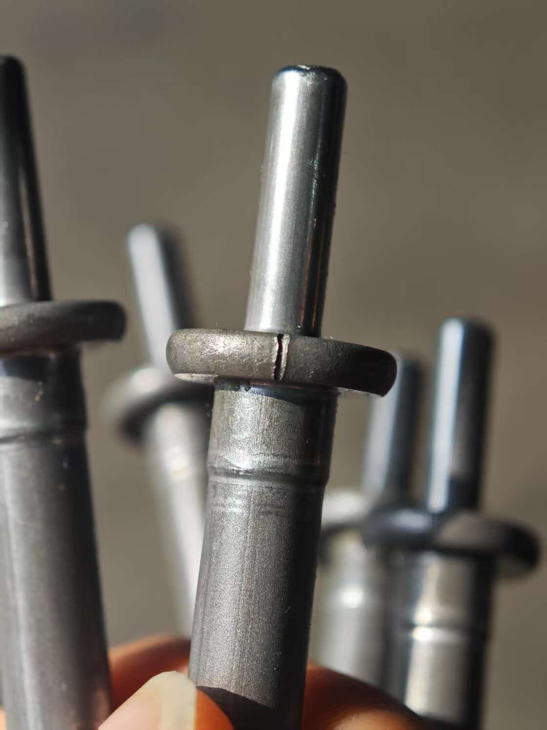
Retain station samples and record crack location, number and distribution. An appearance photograph defines the symptom; it does not establish its cause.
Make records, samples and tests correspond
Retain identified wire, cut blanks, samples from the relevant stations and defective parts. Final parts alone may conceal an earlier origin. Connect the heat, processing route, coil and test results. Select surface, section, microstructure, fracture or mechanical tests to answer the specific question.

A tensile comparison may assess tensile strength, elongation or reduction of area according to the selected method. Confirm equivalent sampling and material condition. A hardness investigation must identify the method, section, test points and conditions.

The tensile and microhardness photographs illustrate test methods; they are not corresponding results for the cracked part shown here. A single measured value cannot replace the complete comparison.
Design a useful comparison
| Record group | What to retain |
|---|---|
| Material and sampling | Batch, coil, delivery condition, location and sample identifiers. |
| Product and process | Drawing, blanks, station samples and actual operating conditions. |
| Changed factors | Before-and-after settings, with the main change isolated where practicable. |
| Continuous production | Parts produced and inspected, abnormal count, time and location. |
Where the established process and safety conditions allow, compare material with a stable history and the material under investigation under both sets of conditions. Check whether the difference repeats and follows the material, operating conditions or their interaction. Changing material, speed and lubrication together may restore production but does not identify the effective factor; record any necessary combined change and verify it later.
Match the material to the whole manufacturing route
Lower flow stress can help some operations, but minimum hardness is not a universal objective. Consider microstructure, surface quality, dimensions, coating, subsequent operations and final properties. For products relying on the delivered condition for final performance, reducing hardness without checking those requirements can be inappropriate.
Creation Group links traceable supply records and material tests with the customer’s drawing, operating conditions and stage samples. Provide grade, size, batch, product drawing, wire and defect photographs to define a purposeful comparison before choosing corrective measures.
Technical references
- Nippon Steel Technical Report 116: medium-carbon wire rod for cold heading
- Ruan and colleagues: coating-based lubricant evaluation using the localised rod-drawing test
These sources provide material-development and lubricant-test context. They do not validate a particular customer material, machine comparison or production result.